The Logic Green chips are enhanced clones of the Atmel ATMega328 chips, used on Arduinos such as the Uno and Nano. The Logic Green chips will mostly run the same code as the Atmel chips, but they can also operate faster, optionally on a lower supply voltage, and have extra features such as true analogue output (not just PWM imitating analogue).
They come with a serial bootloader, but if you want to change the fuse settings, or upload a program without using the bootloader, or burn the bootloader back to a chip that’s lost it, then you can’t use the Arduino standard USBasp. The LGT chips use a different ISP that connects to pins labelled SWD and SWC.
I used the program written by David Buezas, https://github.com/dbuezas/lgt8fx based on work by brother_yan https://github.com/brother-yan/LGTISP and Randall Bohn.
You’ll find stuff on various websites about needing to edit a standard Arduino toolchain file: HardwareSerial.h but I found that with newer versions of the IDE anyway (I’m using 1.8.19 at the time of writing), and the code I downloaded, there’s no need to do that. But the process can be a bit confusing. These are the steps you need to build a working ‘programmer’. Ideally, you want two of the Nano-style boards, or the Micro-style boards with a USB-to-serial interface attached. You can temporarily set up one of them as a programmer to upload the program to the second. The second one can then be kept as a dedicated programmer, and you can’t accidentally overwrite its own program by doing a serial upload, because its serial bootloader will no longer be present.
Even if you’ve already installed other board manager URL’s for working with LGT8F chips (using the serial bootloader), you’ll need to add David Buezas’ lgt8fx package too. It’s easy, and you only need to do it once. In your Arduino IDE’s File->Preferences menu, click on the little icon to the right of the Additional Boards Manager URLs: and add this line after any that are already present (or as the first line if you’ve never added any before):
https://raw.githubusercontent.com/dbuezas/lgt8fx/master/package_lgt8fx_index.json
Click OK to close the Additional Boards Manager URLs window, then OK again to close the Preferences Window.
In the IDE’s Tools->Board: Boards Manager… window type LGT8fx in the filter/search box, and you should see LGT8Fx Boards. Install the latest version available. My version was 1.0.6 at the time of writing.
Now you can set up to program sketches to your LGT8F328 in the normal way:
Tools->Board:->Logic Green Arduino AVR Compatible Boards->LGT8F328
Tools:->Clock Source:->Internal
Tools:->Clock:->32 MHz
Variant:->328P-LQFP32 (e.g. MiniEVB nano-style and WAVGAT)
Arduino as ISP:->Default (64)
Port:->(whatever port your board is at)
Programmer:->AVR ISP
This should let you upload any normal programs, for example, blink to test out that it’s working. I found with these settings there’s no need for the clock_prescale_set(clock_div_1); instruction described by Ralph Bacon in his video – the board automatically runs at 32MHz, and Serial baud rates and millis(); etc. work correctly. If you want the board to run at 16 MHz (or 8, 4, 2, … MHz) just change the Tools:->Clock option, and leave everything else the same.
When you’re ready to upload the LarduinoISP program to your board, so you can use it to program other LGT8F328 chips, just alter the Tools:->Arduino as ISP: option from Default (64) to [To burn an ISP] SERIAL_RX_BUFFER_SIZE to 250
If you forget to change the option back after uploading the LarduinoISP sketch, then everything will still work, but all your sketches that use Serial will waste RAM by making the buffer bigger than it usually needs to be.
I noticed that the lines that control the status LEDs of the LarduinoISP programmer had been commented out. I put them back in again. Even if you don’t fit the LEDs, they don’t do any harm. You can download my edited version of the LarduinoISP sketch here: https://ceptimus.co.uk/LarduinoISP.zip
Once you’ve programmed your LarduinoISP, you can switch the Tools:->Arduino as ISP: option back to Default (64). Program other LGT8F328 chips attached to your LarduinoISP by using the ‘Upload using programmer’ option of the Arduino IDE.
Connections:
| LarduinoISP pin | Target board connection (or other) |
| 10 | PC6/Reset |
| 12 | PE2/SWD |
| 13 | PE0/SWC |
| 9 | (via 1k resistor) Green ‘heartbeat’ LED (to GND) |
| 8 | (via 1k resistor) Red ‘error’ LED (to GND) |
| 7 | (via 1k resistor) Yellow ‘programming’ LED (to GND) |
When you upload a sketch to a target using the LarduinoISP programmer, then it no longer has the serial bootloader. You can reinstate the serial bootloader by using LarduinoISP to ‘burn bootloader’ to the attached device.
If you’re going to use LarduinoISP a lot, then it’s a good idea to use one LarduinoISP to upload a copy of LarduinoISP to a second target device, that also possesses a built-in USB serial port. Then that second device becomes your dedicated programming tool, and you can’t overwrite its sketch by accidentally doing ‘Upload’ instead of ‘Upload using programmer’. If you do that, it’s worth permanently soldering on the LEDs, and a lead that brings out pins 10, 12, 13 plus VCC and GND to a standard connector that fits the devices you wish to program. Of course, for the one-off operation of compiling LarduinoISP and ‘uploading using programmer’ it to a second board, you again need to temporarily set the option:
Tools:->Arduino as ISP: option from Default (64)
to
Tools:-Arduino as ISP: [To burn an ISP] SERIAL_RX_BUFFER_SIZE to 250
(and change it back to default again afterwards).
I built a compact ISP SWD interface using one of the ‘micro’ LGT8F328-P – SSOP20 boards. Of course, that board doesn’t have a built-in USB-to-serial converter, but I mated it to one of the USB-serial interface boards that uses a CP2102 chip.
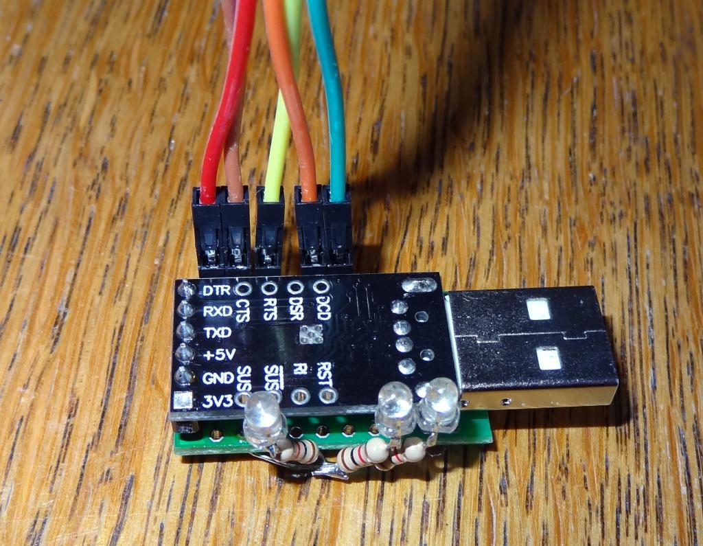
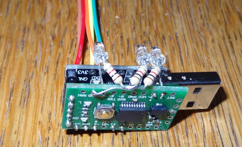
The pinout of the CP2102 board perfectly matches the ‘serial end’ of the micro LGT8F board, so they just have to be soldered together in piggy-back fashion. I added the green ‘heartbeat’, yellow ‘programming in progress’, and red ‘error’ LEDs, complete with their resistors – though, of course, you don’t really need to fit the LEDs at all. I’ll probably 3D print a little case for it!
It works great for uploading sketches and burning bootloaders. I tried it on both the ‘Nano-style’ and ‘Micro-style’ boards, and it worked perfectly every time.
The micro board doesn’t have all the pins that the original sketch uses to connect to the SWD programming port of the target device, nor the LEDs. I altered the I/O allocation slightly. If you want to build one, the documentation of which pins to wire to is all included in the sketch: https://ceptimus.co.uk/LGTisp.zip
Leave a Reply