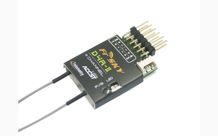
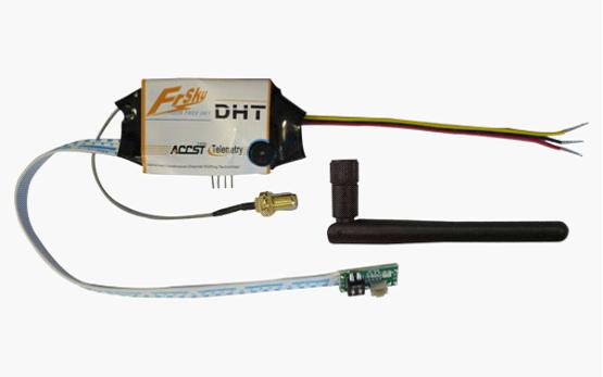
I used a FrSKY D4R-II receiver and a DHT DIY Tx module with an Arduino Pro Mini for the purpose of this post. These FrSKY products use the older “D mode” telemetry and the DHT module is now discontinued, but I’ll be updating this post to deal with the newer S.Port Telemetry soon.
There are still lots of people using the older “D mode” equipment and in any case the Arduino code shows the general approach to decoding serial data on any digital pin. The code presented should work on any of the ATmega-based Arduinos: Uno, Nano, Pro Mini and so on…
First thing to be aware of is that the Telemetry data where it emerges from the transmitter module on the Txd pin is designed to be connected to a PC-type RS232 port. It works at voltage levels of about +6V swinging to -6V. Don’t connect it directly to your Arduino! It could damage either the module or the Arduino!
Fortunately the only ‘interface’ needed to connect the signal to the Arduino is a humble 100k resistor. This limits the maximum current flow to 60 microamps and the ATmega’s protection diodes on each I/O pin then safely clamp this to the Arduino’s 0V to 5V range. This is a method approved by the chip manufacturers, Atmel – indeed they even suggest that mains voltages can be connected to the chip through a suitable limiting resistor in an application note: http://www.atmel.com/Images/Atmel-2508-Zero-Cross-Detector_ApplicationNote_AVR182.pdf
So for the purpose of this post we connect the signal from Txd through a 100k resistor to Arduino Pin 11 (you can choose any digital or analogue pin with small modifications to the code), and you need to connect the GND pin from the module to GND on your Arduino.
We use setup() to initialize an interrupt handler to respond to changes of signal on pin 11, to initialize a few variables and start a Serial port where we can display things:
void setup(void) {
  pinMode(11, INPUT); // serial input (Digital 11 is Port B, bit 3)
  PCMSK0 = 0x08; // set mask to allow (only) digital pin 11 pinchange interrupts on Port B
  PCICR |= 0x01; // allow pinchange interrupts for Port B
  rssi = a1 = a2 = 0;
  timeout = 1000; // ms
  Serial.begin(115200);
  oldMillis = millis();
}
The interrupt handler decodes the incoming serial characters (remember the mark and space levels are swapped compared to standard Arduino serial). Don’t bother understanding this code unless you’re specially interested – all it does is decode individual 8-bit characters arriving and call handleRxChar() to handle each individual character that arrives:
ISR(PCINT0_vect) { // Port B pinchange interrupt
  static uint8_t prev = 0;
  static uint8_t currChar = 0;
  static uint8_t currBits = 0;
  uint8_t now = TCNT0;
  sei(); // allow other interrupts once time has been captured
  uint8_t bits = (((uint8_t)(now - prev)) + 13) / 26; // at 9600 baud with 4 uS TCNT, one bit is 1E6 / (4 * 9600) = 26.04 counts, so half a bit is ~13 counts
  if (!bits || bits > 9) { // detect 0 bits when gap between characters and TCNT0 wrapped exactly, also limit bits to 9 to prevent overflow of (currBits + bits)
    bits = 9;
  }
  prev = now;
  if (!(PINB & 0x08)) { // -ve edge, but inverted RS232 so preceding data bits were low
    if (!currBits) { // start of char so bits includes the start bit (start bit is low)
      currBits = 1; // currBits count does includes the start bit
      bits--; // but don't include start bit in character decode
    }
    currChar >>= bits; // received low bits represent '0' in character.  LSB arrives first, MSB last
    currBits += bits;
  }
  else if (currBits) { // preceding data bits were high
    if (currBits + bits > 9) { // trim stop bit if receiving character values >= 128 (MSB will be high and stop bit is also high)
      bits = 9 - currBits;
    }
    currChar = (0xFF00 | currChar) >> bits; // received high bits represent '1' in character.  LSB arrives first, MSB last
    currBits += bits;
  }
  if (currBits > 8) { // start bit plus character received
    uint8_t rxChar = currChar; // don't know if interrupt is re-entrant - if not then this won't help but if it is then allows next bit(s) to be received while handling char
    currChar = currBits = 0;
    handleRxChar(rxChar);
  }
}
Now we come to the FrSKY specific stuff – FrSKY data arrives in 9-byte packets framed by hex 7E characters. Of course the value 7E might be included in the data, but can’t be sent directly as it would be mistaken as a framing byte. To get around this, FrSKY uses a technique called byte stuffing where 7E is replaced by the pair 7D 5E. That means that 7D now also can’t be sent directly as a data byte as it would be mistaken for the character introducing byte stuffing – so 7D is replaced by the pair 7D 5D. This code replaces any pair of byte stuffing codes with the single byte original and when it sees a full 9-byte data packet framed with 7E it passes that packet on to handlePacket() for further processing:
void handleRxChar(uint8_t b) { // decode FrSky basic telemetry data
  static uint8_t packetPosition = 0;
  static uint8_t packet[9];
  static bool byteStuffing = false;

  if (b == 0x7E) { // framing character
    if (packetPosition == 9) {
      handlePacket(packet);
    }
    packetPosition = 0;
    return;
  }

  if (b == 0x7D) {
    byteStuffing = true;
    return;
  }

  if (byteStuffing) {
    byteStuffing = false;
    if (b != 0x5E && b != 0x5D) {
      packetPosition = 0;
      return;
    }
    b ^= 0x20;
  }

  if (packetPosition > 8) {
    packetPosition = 0;
  }
  else {
    packet[packetPosition++] = b;
  }
}
There may be several different packet types when telemetry sensors such as an altimeter are present, but for now we’ll ignore all but the most basic type of packet. This packet type with a signature byte of FE is always present and contains the RSSI (received signal strength indication) and the two analogue voltages AD1, and AD2. As well as the signal strength received by the receiver, this packet also contains the signal strength received by the transmitter – but we’re not usually interested in that – we’re interested in how well the receiver can “hear” the transmitter and not the other way round! The handlePacket function in this example just extracts the byte values for rssi, a1, and a2 and makes them available as global variables.
void handlePacket(uint8_t *packet) {
  if (packet[0] == 0xFE) { // not interested in telemetry data other than the most basic kind for this application
    a1 = packet[1]; // A1:
    a2 = packet[2]; // A2:
    rssi = packet[3]; // main (Rx) link quality 100+ is full signal  40 is no signal
    // packet[4] secondary (Tx) link quality.  Strength of signal received by Tx so not particularly useful.  Numbers are about double those of RSSI.
    cli(); timeout = 1000; sei();
  }
}
All that’s left is to display any received data by printing it to the Serial port so it can be monitored by the Arduino terminal (Ctrl-Shift-M and set the baud rate to 115200). The loop() here uses the millis() millisecond counter to only update the serial display twice per second:
void loop(void) {
  uint32_t now = millis();
  int32_t ms = now - oldMillis; // milliseconds elapsed since last loop
  oldMillis = now;

  if (timeout <= (int16_t)ms) {
    timeout = a1 = a2 = rssi = 0;
  } else {
    timeout -= ms;
  }

  if (ms >= millisTillNextPrint) { // time to print
    if (!rssi) {
      Serial.println("No telemetry data being received");
    } else {
      Serial.print("RSSI: ");
      Serial.print(rssi);
      Serial.print(" AD1: ");
      Serial.print(a1);
      Serial.print(" AD2: ");
      Serial.println(a2);
    }
    millisTillNextPrint += 500 - ms;
  } else {
    millisTillNextPrint -= ms;
  }
}
And that’s it! The complete Arduino sketch is attached here: FrSKY_telemetryDecode
In my next post, I’ll expand on the data packet handling to explain how different types of telemetry sensor data are encoded, and how you can even send your own home-brew telemetry data back to the ground by injecting a serial data stream to the receiver on board your model.
Leave a Reply to antonio Cancel reply