An Arduino-based programmer for the AT89C2051 chip

The Atmel AT89C2051 is a low cost microcontroller in a 20-pin DIL package.  It runs MCS-51 (commonly termed ‘8051’) code.  It works from 2.7V to 6V at anything from 0 Hz up to 24 MHz.  It has 2K bytes of Flash memory to hold the program and 128 bytes of RAM.  It has 15 I/O lines, a UART, an analogue comparator and two 16-bit timer/counters.

I came across the chip as it’s often used in cheap 7-segment clock kits such as this one from BangGood (only £2.71 at the time of writing).

I wanted to reprogram the chip so I could use the kit as a stopwatch/timer instead of a regular clock.  Of course I could have bought a programmer to do the job, but reading the chip’s data sheet it seemed straightforward to do the programming with an Arduino – and I thought it would be a fun project to do that.

The chip is programmed a byte at a time by setting up each byte on 8 of the chip’s I/O lines and then pulsing some of the other I/O lines to ‘burn’ the byte to flash memory and move on to the next byte to be programmed.  You can also read the existing program out of a chip (unless a read-protect bit has been set) and there are special ways of pulsing the I/O lines to erase the whole chip and so on.

The only tricky thing is that one pin has to be raised from the nominal operating voltage of five volts up to twelve volts during programming – the challenge was working out the easiest way to do this using an Arduino.

So I decided to use an Arduino Mega 2560 for this project.  A Uno doesn’t have quite enough I/O to do the job properly, and the Mega 2560’s double row of I/O pins makes routing the connections to the chip simple as the chip can sit directly over the double-row connector.

I decided to use a charge pump (voltage multiplier) running off the Arduino’s five volts to generate the programming voltage – that seemed cleaner than needing a separate twelve volt supply.  It just uses a few diodes and capacitors and relies on the Arduino pulsing some of its I/O lines to drive the voltage multiplier.  A couple of zener diodes clip the voltage down to exactly 5V or 12V and a couple of transistors, also switched by the Arduino, select between either of those voltages or 0V to drive the pin on the chip.

I designed a PCB using the free KiCad package.  Here’s a .pdf of the circuit diagram, and here is what KiCad produces as a picture of the design.  In the picture it looks like the chip to be programmed is soldered straight into the board, but of course in reality a ZIF socket is fitted in that position so that the chip(s) you are programming can be quickly swapped.

programmer3DThat picture wrongly shows the tracks on the top of the board – I design them that way for home production as the transfer process mirror-images the tracks so that they’re correct for the back of the board.  If you fancy making one of your own, it would be quite straightforward to  do it on strip board – like I say most of the pins of the chip just connect direct to the Arduino pins that the chip sits over.  If you want to etch your own PCB, here is a .pdf of the mask.

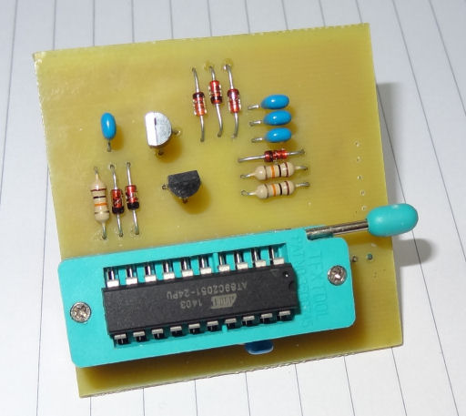
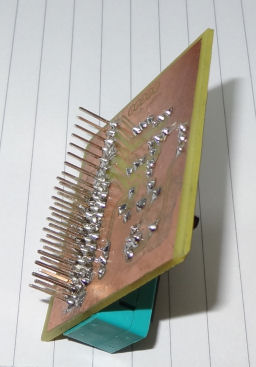
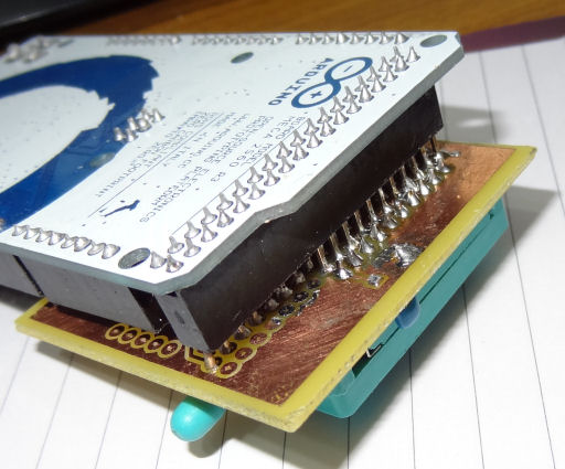
Here are a couple of snaps of the prototype board.  You can see I didn’t bother to crop back the board edges!

topback
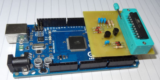
And this is what it looks like when docked on top of the Arduino Mega 2560.

topDockedbackDockedSo that’s about it for the hardware.  I’ll make a separate post about the Arduino sketch that does the work of programming the chip, and the PC program that talks to the Arduino to send and receive hex files.

Part 2


Posted

in

,

by

Tags:

Comments

30 responses to “An Arduino-based programmer for the AT89C2051 chip”

  1. Noah avatar
    Noah

    What program do you use to write the code in?

    1. ceptimus avatar
      ceptimus

      I used the demo version of the Keil C compiler to write the 8051 code, I use the Arduino IDE to write the Arduino code, and the free version of Microsoft Visual Studio to write the PC program (using the C# language).

      1. Noah avatar
        Noah

        Thanks for the reply. So I’m using an arduino mega and a couple of relays to switch the reset pin to 12 5 or 0 volts but it’s not working. Could it be the relays are to slow or something else.

  2. Noah avatar
    Noah

    Can I have a copy of the test code you used for the at89c2051. It would be much appreciated.
    Thank you.

  3. putro adi avatar
    putro adi

    please, may i know what your code to operate the digital clock? thanks

    1. ceptimus avatar
      ceptimus

      I have the code and the clock somewhere, but I’ve not used it for many months. I will try to blog about it and post the code I wrote, but I can’t promise when I will be free to do it.

    2. MOHD YOUNIS DAR avatar
      MOHD YOUNIS DAR

      @ceptimus how much programming is needed , is it arduino programming , keil or c language which one to use. Can I remove my arduino uno MC ic and replace with this one (89C2051) to program it or I must use only ide.

  4. hexdef6 avatar
    hexdef6

    Could this be used for the 55wd chip as well with modification

    1. ceptimus avatar
      ceptimus

      Yes, it looks like the programming sequence is the same. Obviously the board layout would need changing to suit the chip and the programs modified a bit to suit the extra memory capacity of the chip.

  5. aldolo avatar
    aldolo

    i had exactly the same idea. this clock kits are priced 1$ shipped. not bad for the fun. unfortunatly i’ve already ordered some digispark arduino and clock boards to build my timers but i think at least a couple of AT89C2051 will follow soon.

  6. Victorramon avatar
    Victorramon

    I alwais got an error when running the software as follow:
    An unhandled Microsoft .Net framework exception occurred in AT89C2051programmer.exe[1760]. Just-in-Time debugging this exception failed with the following error:Not installed debugger has just-in-time debugging enabled.

    I have windows10 prof.

    Any idea ??

    Thanks in advance

    1. ceptimus avatar
      ceptimus

      Probably your best bet is to download the source code, here: http://ceptimus.co.uk/AT89C2051ProgrammerSource.zip and run it from inside Visual Studio. Visual Studio is free and even if you’ve never used it before it’s pretty easy – just open the project and click the run button. If / when an error occurs, it will show you the line it occurred on and the cause of the error. If you don’t understand the error just report back here what you see and I’ll try to fix it. It will be much easier for me once I know where in the program the error occurs on your system.

  7. Ahmed avatar
    Ahmed

    I have a lot of 20 pins, but because I had an old parallax programmer and it was not working anymore, I left them. I happened to come across this article and thank you for it. I’m going to make this programmer with Atmega328 or Arduino Nano, which is smaller and in one package, but I’m having trouble changing the pin config and needing help.
    I saw another project with Arduino Uno, https://github.com/tardate/LittleArduinoProjects/tree/master/8051/AT89C2051/Programmer
    but it’s Python’s app that I do not know and I do not know what to set up. I also saw that pins P3.1 and P3.0 were not used, and also vcc can be directly connected.
    I need to decrease more pins. I might have to use a separate charging pump circuit.
    thank you

  8. Kuntal Chatterjee avatar
    Kuntal Chatterjee

    Thank You, the best AT89c2051 programmer.

  9. MOHD YOUNIS DAR avatar
    MOHD YOUNIS DAR

    Is it better to use separate 12 v power supply or should I use charge pumping from arduino UNO board and if code can be written directly from arduino then what is the fun of using keil or c-language programming?? Please help me solve this issue.

    1. ceptimus avatar
      ceptimus

      Use a separate 12V supply if that is easier for you and you already have one. Use the charge pump method if you want a self-contained unit and don’t mind building the slightly more complex board with the extra diodes and capacitors. The arduino is only a method of getting the hex file into the chip. You still need a separate compiler or assembler to create the AT89C2051 code. The only reason for programming AT89C2051 chips (for me) is because I already have some hardware that has those chips on board. If you just want to write code and can choose the chip you’re programming, then I recommend sticking with those chips that the Arduino platform supports: either Atmel or ESP8266, ESP32, etc.

  10. Arang avatar

    “Look like to hard to use..can I use for atmel series at89cxx..?thanks.

  11. Anandhanking avatar
    Anandhanking

    Bro….can you plz edit the code and schematic for using relay’s NO and NC connections instead of using charge pump…. That way we can give 12 or 5v without sorting the supplies…. Plz bro edit and send schematic and code bro….thx

    1. ceptimus avatar
      ceptimus

      Even if you have a separate 12V supply available, relays cost much more than transistors, plus they are larger, heavier, slower and less reliable. I won’t be making that change, but if someone else wishes to do it then please go ahead.

  12. […] I first mentioned these kits about six years ago when I blogged about making this Arduino-based programmer for the AT89C2051 chip. […]

  13. Fredy avatar
    Fredy

    Con un Arduino nano puedo leer un at89c2051 ? Tú me podrías ayudar muchas gracias

    1. ceptimus avatar

      Un Nano puede leer el AT89C2051 a menos que se haya configurado el bit de ‘protección del programa’. A veces, el bit de protección se establece porque los fabricantes no quieren que la gente copie su código.

      1. Fredy avatar
        Fredy

        Como debo hacer la conexión entre el Arduino nano y el at89c2051 para poderlo leer le agradezco su ayuda

        1. ceptimus avatar

          Voy a hacer un video mostrando como hacerlo. Recuerde, sin embargo, que algunos proveedores configuran ‘bits de bloqueo’ en el AT89C2051, y luego el dispositivo no se puede leer, aunque aún se puede reprogramar.

          1. Fredy avatar
            Fredy

            Le agradezco cuando esté el vídeo si me regalas el link para verlo

          2. Fredy avatar
            Fredy

            cuando esté el vídeo si me regalas el link para verlo estaría muy agradecido y me ayudarías a salir de un problema que tengo

    2. ceptimus avatar

      https://youtu.be/r0WQi8ouEnQ

      Download link is in video description.

  14. ceptimus avatar

    https://youtu.be/r0WQi8ouEnQ

    Download link is in video description.

Leave a Reply

Your email address will not be published. Required fields are marked *