This is the kit that uses the STC15W201 (or STC15W204) chip. The -201 has only 1K of FLASH memory for program storage, the -204 has 4K. The chips are interchangeable and have the same pinout – they only differ in the amount of FLASH (and EEPROM) memory they contain.

New patterns since making the video! Download hex file to see them!
The kit comes in two varieties: the older kit came with a DIL package chip, and a chip socket to mount it in. This made it easier to solder than the newer surface-mount-chip version. However, the surface mount version tends to have the -204, so there’s more room for your program to grow.
You can get the chips cheap from places like AliExpress, so if you have the -201, you could consider buying an upgrade. However, I’ve put a version of my code below that works with the -201: it just has fewer patterns than will fit in the -401.
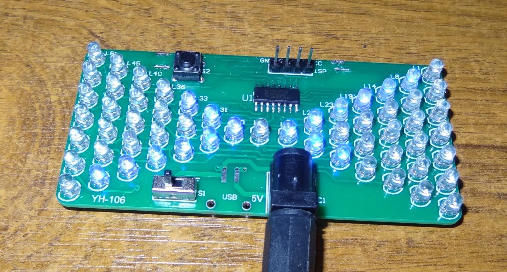
As supplied, the kit only has one pattern – an animation of an emptying hourglass. The animation can be run at three different speeds selected by pressing the push button. The board has a programming port, so all you need to change the program is a USB-to-UART adapter (5V or 3.3V – not an RS232 one) such as an FTDI or CP2102 – these are available on eBay etc., or you could use an Arduino Uno or Nano, which has such a chip on board.
The STC15W201 and 204, in common with most of the chips from STC micro, run 8051 code. The original 8051 was made by Intel and was a very popular chip in the 80s and 90s. Most of the STC chips (including the STC15 range) run much faster than the original Intel chips, and have extra on-board peripherals and other enhancements.
You can write a progam for the chip in C, either using the Keil compiler, or SDCC. The Keil compiler is Windows only, commercial, and expensive – but you can use the free evaluation version for small projects like this one. SDCC is free and available for most operating systems. Both compilers produce Intel Hex files which are then sent to the chip. To write the hex files to the chip you can either use the STC isp tool (on Windows) or stc8prog from both Linux and Windows. I prefer to use SDCC and stc8prog.
Once you’ve installed SDCC, compiling your code is easy. Just use your favourite text editor to create/edit a file, say myprog.c and then at a command prompt enter: sdcc myprog.c
That’s it! SDCC will produce a bunch of files in the current folder, including an assembler listing, and the all important myprog.ihx file which is the one you send to the chip. stc8prog can send the .ihx file, but some programming tools prefer the slightly different .hex format files. You can easily create a .hex file from a .ihx one: just enter: packihx myprog.ihx > myprog.hex
To use stc8prog to send your file to the chip, use the command:
stc8prog -p /dev/ttyUSB0 -e -f myprog.ihx
The -p option selects the serial port to use (this will be something like COM8 on WIndows); the -e option tells stc8prog to erase the flash memory before programming it (this is a required option for the STC15 chips), the -f option specifes the name of the hex file to be written to the flash memory.
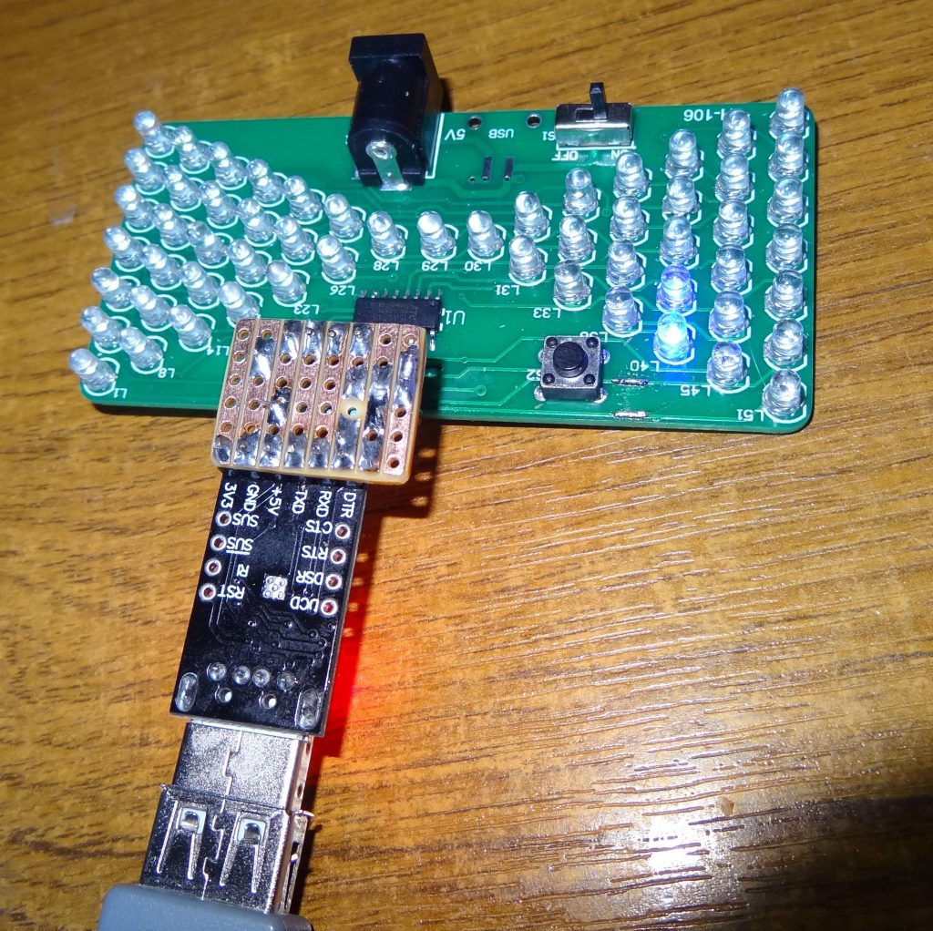
stc8prog will prompt you to cycle the power to the MCU (target chip). You can just unplug and replug the programming interface to the chip to do this (just the GND wire from the programming chip and leave the others connected). Don’t connect any other power supply to the hourglass board while programming – the USB-to-UART programmer provides the necessary power. You have to cycle the power to the STC chip to get it to listen for a programmer – it only does this at startup.
Just connect VCC (or +5V, +3.3V, etc) from the UART to VCC on the ISP connector of the hourglass board, GND to GND, TXD to RXD, and RXD to TXD. If it doesn’t work, try swapping TXD and RXD – some UART boards are labelled with what the signal should connect to, rather than what the signal actually is.
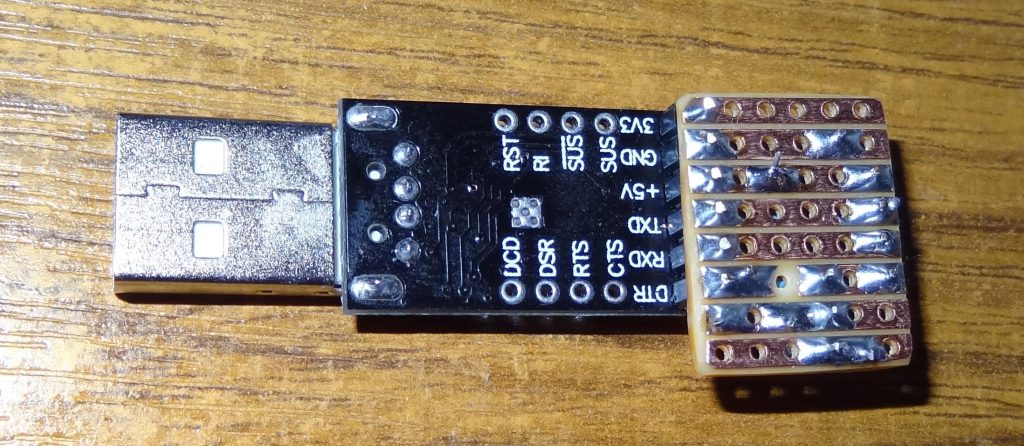
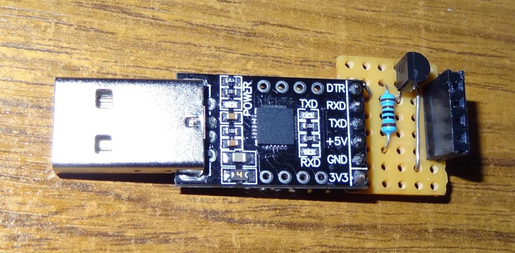
If you’re going to do lots of programming, you can make a little adapter board to put the pins in the right order. If you add a resistor and an N-channel MOSFET, such as a 2N7000, then stc8prog can automatically cycle the power to the chip for you (by using the UART’s DTR line) whenever you use it to send hex files to the chip. I recommend making such an adapter if you’re going to play with STC chips – the same adapter will fit most STC boards, though sometimes you have to swap TXD and RXD over, as not every STC dev board is consistent.
Here are pictures of both sides of my programming adapter board, and a circuit diagram, should you wish to make one.
VCC --o      o-- MCU GND
      |      |
     .-.     |
     | | 1k  |
     | |     |
     '_'     |
      |      |
      |   ||-+
DTR --o --||<- BS170/BSS138/2N7000
          ||-| (N-CH MOSFET)
             |
             |
GND ---------o
Circuit and circuit diagram copied from https://github.com/grigorig/stcgal/blob/master/doc/FAQ.md
To ask stc8prog to cycle the power for you, add the -r (reset) option with the time (in milliseconds) to power down the device. For example:
stc8prog -p /dev/ttyUSB0 -r 50 -e -f myprog.ihx
Writing the program
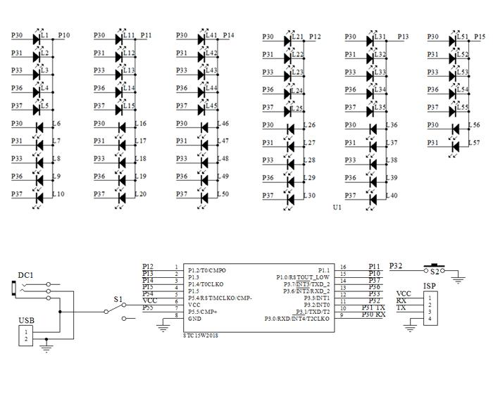
The hourglass board has fifty-seven LEDs, any combination of which the microcontroller can light, using just eleven I/O pins: the whole chip only has sixteen pins, and some of those are used for power, and sensing the push button. How does it do this? First, take a look at the circuit diagram.
One odd thing to note, is that there are no current-limiting resistors. The board is just relying on the chip’s I/O pins having built-in current limiters – and that current low enough not to damage the LEDs. Many microcontrollers would burn out if used them like this; but the STC15’s I/O is able to operate this way without apparent harm. It’s probably a good idea though, for both the health of the chip and the LEDs, to reduce the supply voltage to the board when it’s operating for long periods. I found my board was happy to work with a supply voltage of just 2.7V
As usual, when a microcontroller is driving lots of LEDs (multiple digits of seven-segment displays, for example), the LEDs are multiplexed: they’re laid out in rows and columns – to light a particular LED, the microcontroller has to make, say, the LED’s ‘column’ pin high, and its ‘row’ pin low at the same time. This allows the microcontroller to drive many more LEDs than it has I/O pins.
The LEDs cannot all be lit at the same time: the microcontroller has to switch on each (say) column in turn, and then activate the appropriate rows for that column where there are LEDs that should be lit; then, a moment later, it can switch to the next column. If it does this fast enough, then the human eye cannot see that the LEDs are actually flickering on and off at high speed: a LED flickering on and off at a frequency greater than about 30Hz, appears to the eye to be constantly on.
The hourglass kit takes this one stage further than a usual LED matrix, by having two LEDs at each row/column intersection, but connected back to front. A LED only lights when its anode connection is at a higher potential than its cathode (2.5V or greater for a blue LED). By having two LEDs at each intersection connected the opposite way around, the microcontroller is able to light one of them by making the column output high and the row output low, and the other by swapping the polarity of the row and column outputs.
To take a specific example, look at LEDs labelled L4 and L9 these are both connected between the microcontroller’s P10 and P36 pins: to light L4, the microcontroller must make P36 high and P10 low. To light L9, it must make P36 low, and P10 high.
The microcontroller uses five ‘row’ outputs: P30, P31, P33, P36, and P37.
The microcontroller uses six ‘column’ outputs: P10 to P15 inclusive.
There could be two LEDs at each row/column junction, for a total of 2 x 5 x 6 or sixty LEDs altogether, but actually only fifty-seven LEDs are fitted, with the last three row/column intersections only occupied by a single LED.
To control this kind of matrix, the I/O pins have to be the so-called ‘tri-state’ type: the microcontroller must be able to power each pin high, power the same pin low, or put that same pin into a high impedance ‘input’ state, where it effectively blocks any significant current from flowing in or out of it.
The original 8051 chip couldn’t do that. Its pins were either powered low, or floating high (with a weak pull-up resistor). When a pin was in the high (weak pull-up) state, then an external device, such as a push button, could pull it low. The same pin could then act as either an output or an input: this was known as a ‘quasi-bidirectional I/O’. Lesser STC microcontrollers, like the STC89 series, are the same.
The STC15 chips achieve the tri-state operation (and more) for their I/O pins, by having three bits to control each pin. Take pin P14 as an example: its standard 8051-like behaviour is controlled by bit 4 of the P1 register, but it has two additional registers P1M0 and P1M1, and bit 4 of both those registers also affects the operation of pin P14. There are three bits for each pin, so eight possible states:
| P1 bit 4 | P1M0 bit 4 | P1M1 bit 4 | Result |
| 0 | 0 | 0 | Output low (strong) |
| 1 | 0 | 0 | Output high (weak) or input (read P1) |
| 0 | 1 | 0 | Output low (strong) |
| 1 | 1 | 0 | Output high (strong) |
| 0 | 0 | 1 | High impedance input (read P1) |
| 1 | 0 | 1 | High impedance input (read P1) |
| 0 | 1 | 1 | Output low (strong) |
| 1 | 1 | 1 | Output floating (open drain) |
For each port register, Px, there are corresponding registers, PxM0 and PxM1.
To control all the LEDs, the program multiplexes in ten stages, numbered 0 to 9:
In stage 0, P30 (the first row output) is output high (strong), and the other P3x row outputs are in their high impedance input state. The six LEDs that can be lit when P30 is high (L1, L11, L21, L31, L41, L51) have their corresponding P1 outputs either output low (strong) (to light the LED) or high impedance input state for not lit.
In stage 1, P30 (the first row output) is output low (strong), with the other P3x row outputs still in their high impedance state. The six LEDs that can now be lit (L2, L12, L22, L32, L42, L52) now have their corresponding P1 outputs either output high (strong) to light the LED or high impedance input for not lit.
Stages 2 and 3 are similar, except that P31 (the second row output) is the one with output high (strong) or output low (strong), and the other P3x row outputs, including P30, are still/now in the their high impedance state.
Stages 4 and 5 use row output P33; stages 6 and 7 use row output P36; and stages 8 and 9 use row output P37.
Note that any one LED can only be lit for 10% of the time (actually a little less, because of the time spent switching to the next row), but by cycling through them fast enough, they don’t appear to flicker.
My program uses a timer interrupt to do the multiplexing. With the chip’s clock set to the standard value of 11.0592 MHz (it can be overclocked up to 35 MHz), the interrupts are set to happen at a frequency of 3.6 kHz, so the overall multiplex cycle (LED flicker rate) runs at 360Hz.
The same interrupt also handles the debouncing of the push button.
The complexity of the interrupt-driven multiplexing can be ignored when controlling the LEDs. There is a simple function setLED(n, state); you just pass LED (numbered 0 to 56) with a state of 1 to turn that LED on, or 0 to turn it off.
The other useful simple function is delayMillis(ms) which delays roughly ms milliseconds (when the chip clock is the standard 11.0592 MHz). ms must be 255 or less. If you need longer delays, call it multiple times.
Source code and hex files
Source code (full version for the -204 chip)
Hex file (full version for -204 chip – too big for -201 chip)
For the -201 chip, here are the pruned-down versions of hourglass to fit inside the smaller flash memory:
Mimic original kit pattern, but with extra speeds, source code
Leave a Reply to Paul Ternest Cancel reply