A radio-controlled plane, powered just by solar cells. There are no batteries. It flies well on bright days, and stays up when there are a few clouds around, but won’t stay up on a cloudy day. The darkest days still provide enough power to work the receiver and servos – even when the plane is inverted – so there’s no need to worry about losing control.
Let’s start with a few photos.
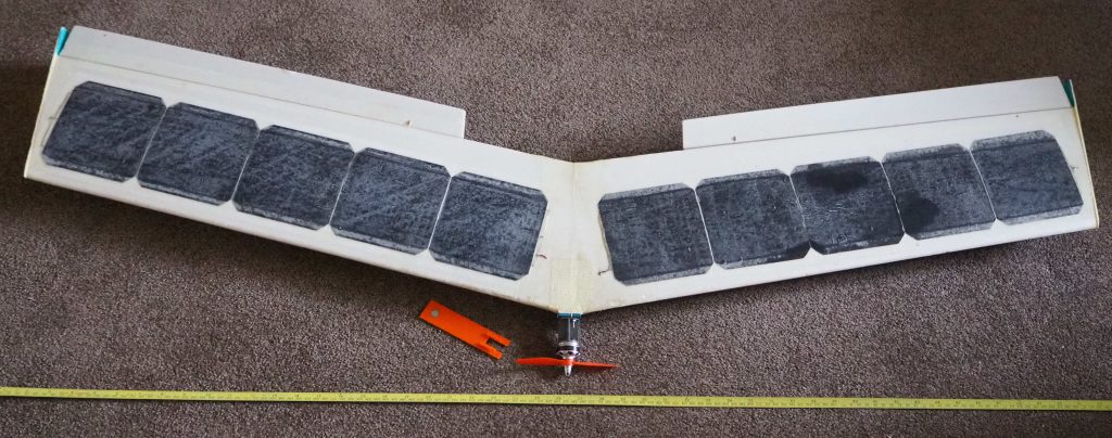
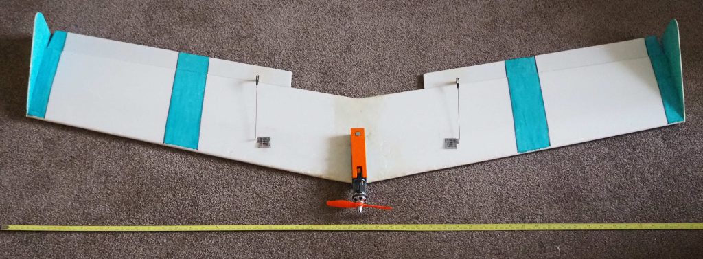
Top and bottom views. The solar cells are on the top of the wing, the colourful part is underneath! Yes, the tip fins face downwards – unusual, I know, but an explanation will follow.
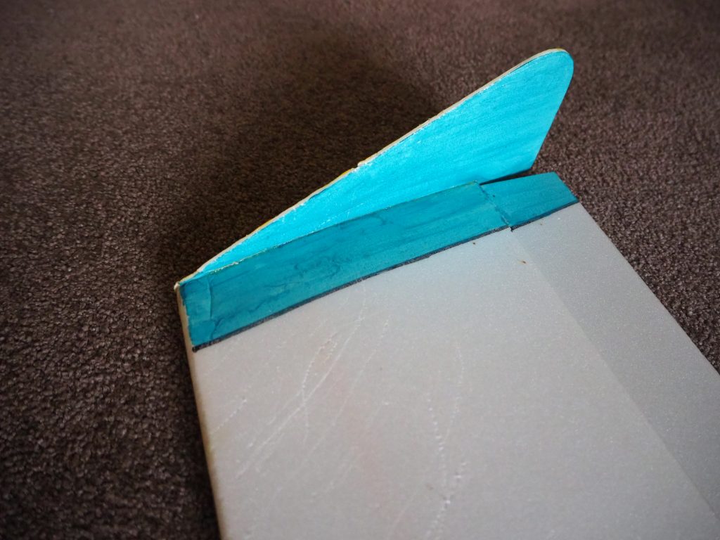
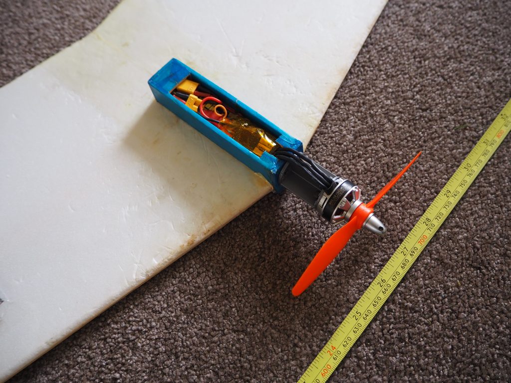
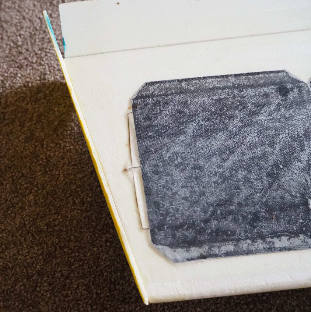
A tip fin, and the small box that holds the electronic parts (with cover removed).
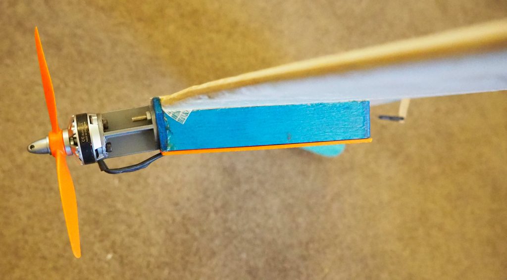
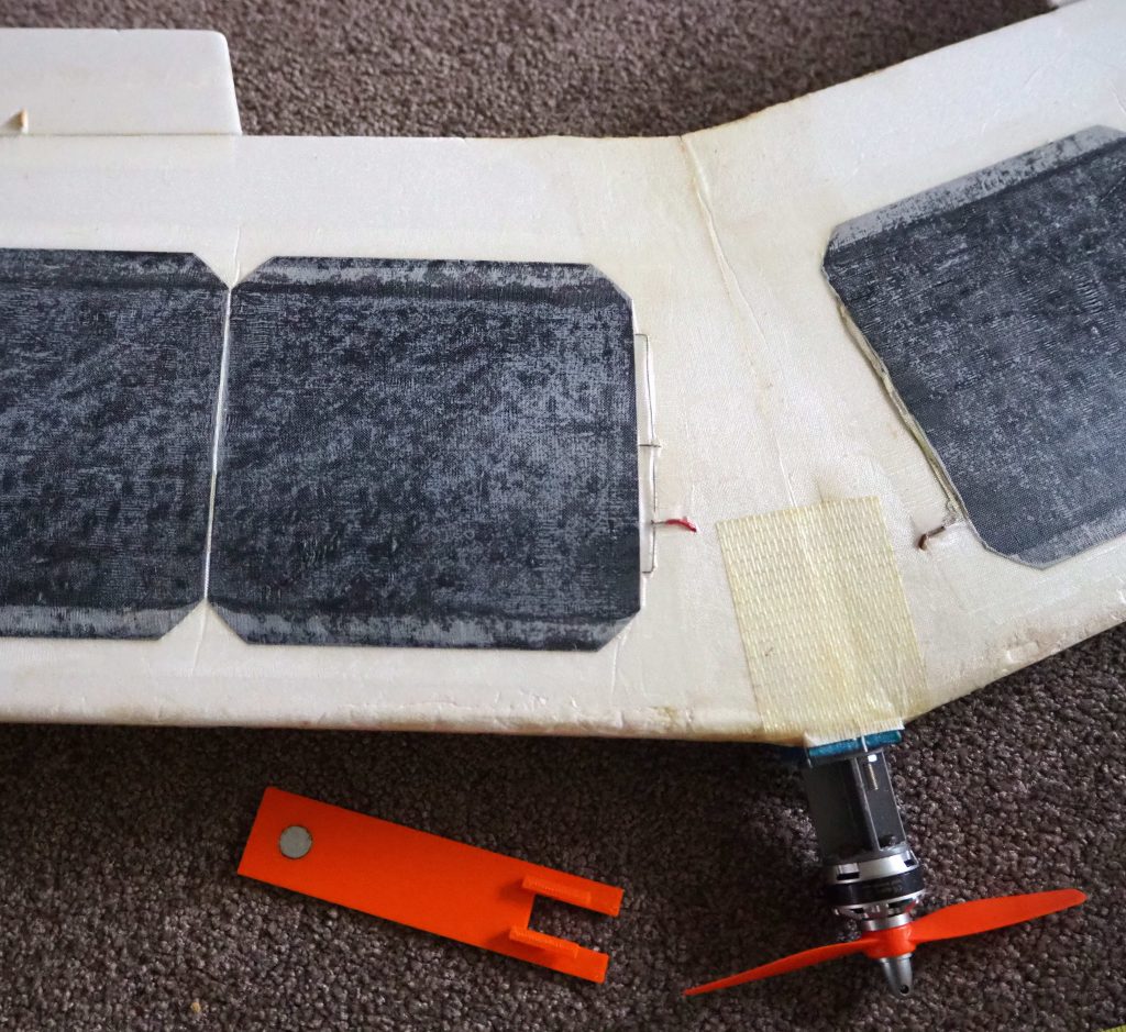
The motor, mounted on its extension piece – this was done to get the centre of gravity in about the right place, without adding nose weight (see notes below). The downthrust angle is six degrees. There is zero sidethrust.
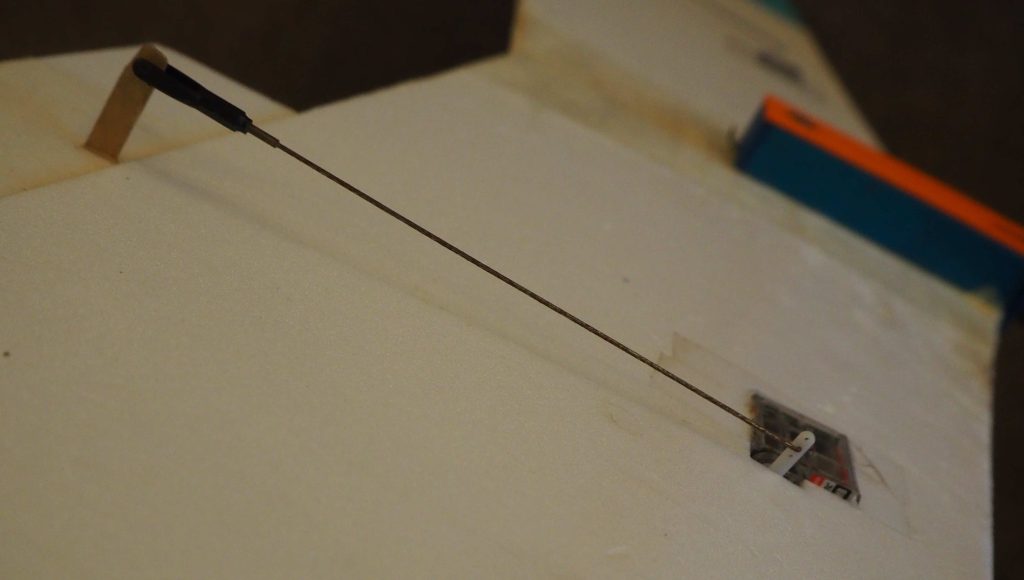
Showing how the servos are mounted, and linked to their elevon controls.
The plane was designed and built by Mike Payne, back in 2018. I played a small part in helping with the power control system, and Mike very generously gave me this plane: it was one of a series of prototypes: first using eight solar cells, then this one (with ten), and then on to twelve cells and one with a delta configuration rather than this flying wing. I’ve flown this one many times over the last seven years, with duration flights of up to two hours, with pilots taking shifts on the transmitter to help overcome boredom! On a sunny day, the plane could remain aloft till the sun begins to get low in the sky – transmitter batteries and pilot boredom allowing.
One lesson from this prototype was that it came out slightly tail heavy – hence the motor extension piece added, rather than adding nose weight. Mike increased the sweep angle of later wings, and also came up with the delta configuration – in both cases eliminating the need for the nose extension. But for this post, I’m documenting the plane I have, so the “plan” and construction details below are for the model photographed above.
The plane needs very lightweight construction to make best use of the limited power available. This plane currently weighs 280 grams (it was lighter in its younger days, but a few running repairs have gradually crept up the weight). The wingspan is 1.35 metres, and the wing area is 0.310 square metres, so the wing loading is only 0.903 kg/m² or about 3 oz/ft².
To achieve this impressively low weight, Mike constructed the plane mostly from 2mm depron sheet. It has upper and lower wing surfaces made of that material, wrapped around a balsa spar, with very thin plywood reinforcement. There are no wing ribs, other than two depron “ribs” at the wing tips, which make it easier to glue on the tip vertical fins. The elevons and tip fins are also made of 2mm Depron. There is some ultra-lighweight glass fibre cloth used to secure and cover the solar cells, and this same glasscloth also acts as a wing join reinforcement bandage, and as the elevon hinges. All the glasscloth is applied using only a thin water-based varnish, rather than the more usual composite resins – again to keep the weight down, and also because many types of resin attack Depron. The minimal “fuselage” is made of thin balsa, with a bit of ply for the motor mount “firewall”. The fuselage cover was originally also thin plywood, but I lost that and replaced it with a 3D-printed one.
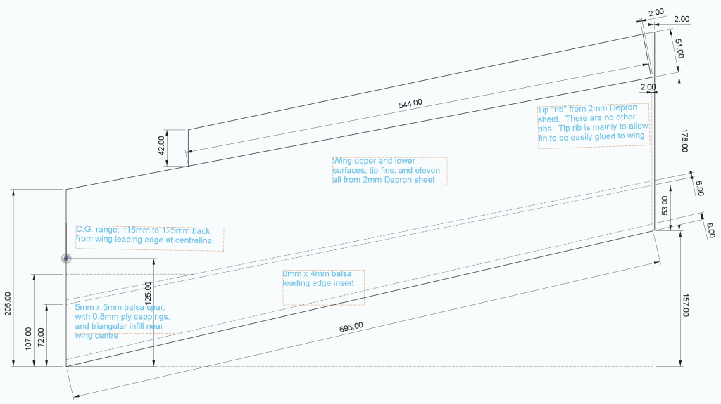
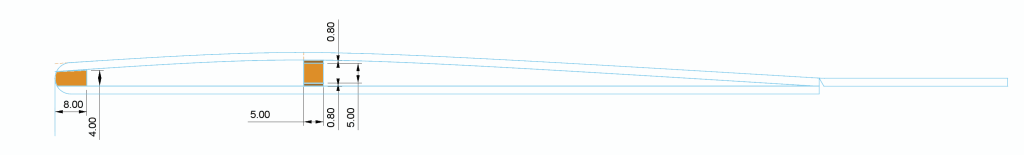
Here you see the dimensions of one half of the finished wing. The upper and lower surfaces can be cut to the same size – the top surface curvature is low enough that it doesn’t need to be cut larger than the flatter bottom.
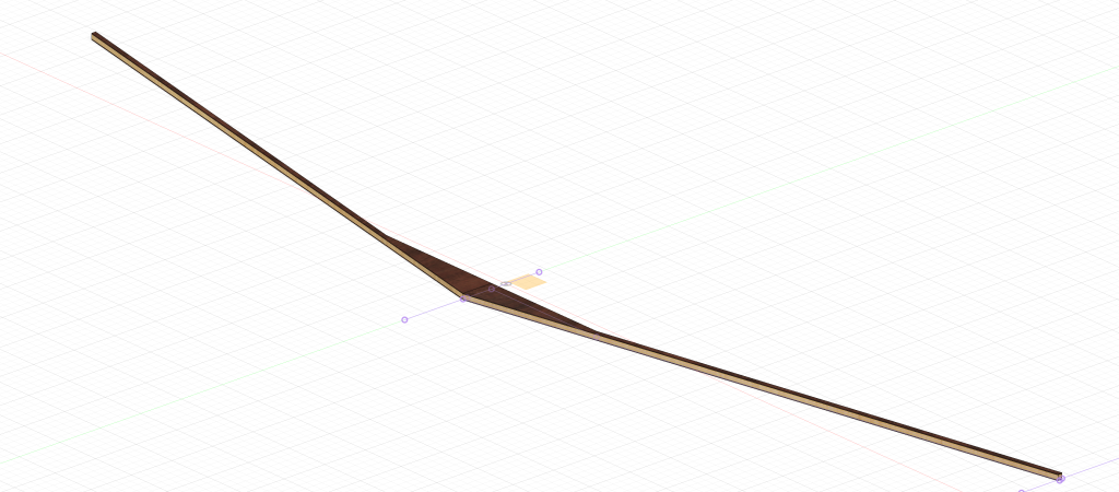
Start by making your wing spar. Mike made his from 5mm square balsa (6mm or 1/4-inch would also be fine). The two half-spars are each 691mm long. They’re joined so that each sweeps back 137.5mm from the centre. Join them flat on a building board (no dihedral). Then add the centre joiner (triangular gusset) with grain running spanwise, cut from balsa sheet the same thickness (5mm / 6mm / 1/4-inch) as the spar. The joiner is 30mm along the model centreline, with the back edge a straight line running spanwise. Mike then applied top and bottom reinforcing plywood plates to the spar, made from 0.8mm plywood (1/32-inch) This is glued to the spar using a very lightweight glue – Mike used Super Phatic Aliphatic glue (by Deluxe), which has the consistency, almost, of water, and dries quickly.
You could, of course, use some other method to construct your spar – maybe carbon fibre tube or similar. It doesn’t need to be fantastically strong, as the plane won’t be pulling high g loads in the air, though mine is capable of basic aerobatics: gentle loops and rolls. The only function of the spar is to add just enough strength to the wing to make it airworthy and a stable platform for the solar cells to be fixed to. Don’t overengineer your spar, or the weight will creep up!
Join the two lower surfaces of the wing, flat, on a building board. Glue the spar down on top of that surface in the position shown above. You can use the same Super Phatic glue for this – it sticks well to Depron. You could use foam-safe cyano, as an alternative, if you don’t like Super Phatic. The Super Phatic has an advantage over foam-safe cyano when you come to attach the top surface, as it gives you a slightly longer set-up time. Only use a minimum amount of glue – it’s surprising how the weight of the glue you use adds up, if you start splashing it around.
On this model, Mike used a small balsa leading edge insert. On some of his other models this was replaced by a strip of Depron. The leading edge is nominally 8mm wide by 4mm thick lightweight balsa sheet/strip, sanded or planed slightly so that it tapers down a little towards the leading edge. This is stuck down to wing lower surface, still held flat on the building board, and once the glue on the spar and leading edge has dried, the wing top surface can be applied, glueing it to the leading edge, the top of the spar, and where it meets the lower surface at the trailing edge. Hold the top surface down with some weights, to keep the whole thing flat, till the glue has dried.
Remember to add some holes and either the electrical connecting wire for the solar cells, or a puller string ready to pull that wire through later. Also, you may wish to cut the holes (in the lower wing surface) for mounting the elevon servos, and again arrange some sort of puller string, ready to pull through the servo wires, once the servos have been mounted.
The above image shows a typical section through the completed wing, after the elevons have been attached. The leading edge is all square during the top and bottom joining process, and then sandpapered to an aerodynamic shape afterwards. The trailing edge is left square. The elevon is only half as thick as the two-surface wing, but it’s just hinged so that the top surfaces are flush, as shown, with a step on the lower surface, at the hinge line.
Although you’ve tried to construct the wing flat on the board, with a flat-bottom wing section, it will inevitably relax into something more like a semi-symmetrical wing, once you remove it from the building board. This is due to the floppy nature of the Depron, and the absence of any wing ribs. For this reason, it’s better to not fit the tip ribs till after the wing has been removed from the board: The tip ribs can then be cut to whatever shape is necessary for them to best fit. The tip ribs are inset between the top and bottom surfaces, and flush with the outer, wingtip, edge: they’re really there just to make glueing on the tip fins more secure.
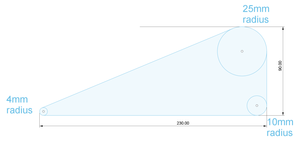
Above diagram shows the tip fin dimensions. The diagram shows the fin upside down compared to its flying configuration – the fins project downwards from the wing tips! Why is this? It’s because shadows falling on solar cells have a disproportionate effect on the power available – even if only part of one of the ten cells is in shadow, it reduces the available power as though all the cells were in that same shadow: it’s the “chain is only as strong as its weakest link” effect.
Large solar panel installations, such as you might install on your house roof, use relays or electronic switches to bypass any (groups of) shadowed cells, so that if the shade of a tree or a chimney falls on some cells, the remaining, unshadowed, ones can continue to operate at full capacity. It’s not really practical to use such a system on a lightweight model plane: you can fit diodes in parallel with each cell, to allow the current to bypass any shadowed ones – but the diodes need to be rated at up to 5A capacity, so they add bulk and weight, and the voltage drop across a diode, when it’s bypassing a cell is about 0.7V, so each shadowed cell loses you about 10% of the available power anyway. Simpler just to avoid shadows which is why the fins point downwards.
The solar cells
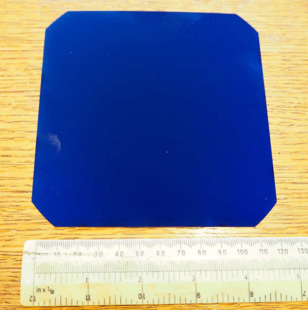
Mike tried a few types of solar cells. Some are ridiculously fragile, and crack almost just by looking at them. The ones he settled on were the Sunpower C60. These still need to be handled carefully, but are much more robust than some of the others – I’ve not broken one in seven years of flying. They also have a high efficiency (relatively high power output) and are readily available at reasonable prices.
Looking at the back, you can see the connections. There are three pads down each side in the image above: All three pads on the left-hand side are electrically linked together, and are the positive output of the cell – you can just see a little + sign on the top left pad in the photo. Similarly, the three pads on the right-hand side are the negative terminal of the cell – they’re also electrically linked together on the solar cell itself.
Although the three pads on each side are linked, you should still connect to all three of them: the traces on the cell are thin and not designed to handle the full current the cell is capable of delivering: as much as five amps in very sunny conditions.
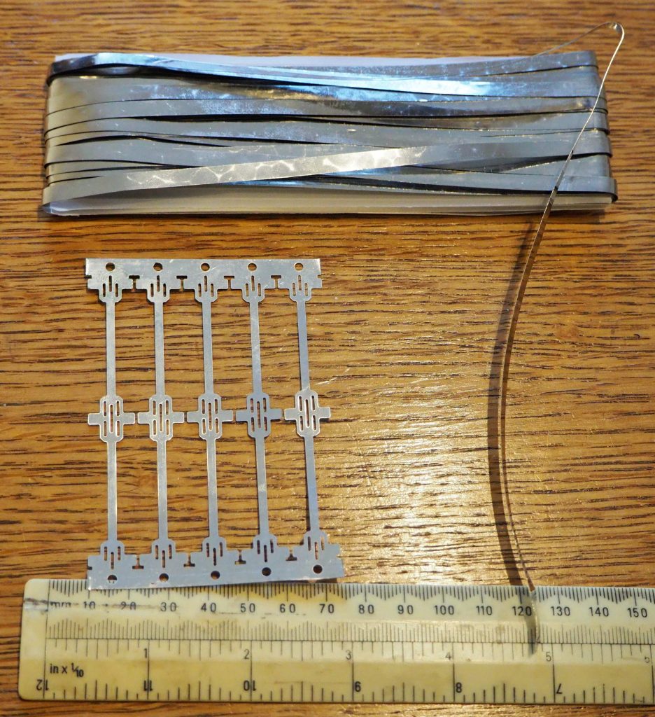
If you buy the cells in reasonable quantities – say twenty or more – they usually come with some nickel-strip joiners – these can be used to connect the cells together in series, either by soldering, or using one of the special spot welders designed for linking together ordinary batteries, should you have access to one. If you use the spot welder, make sure you put the two probes of the welder right next to each other over one pad at a time – if you attempt to pass the welding current between two pads, you’ll likely destroy the solar cell. Soldering is probably safer, if you’re unsure.
So for the ten-solar-cell plane described here, you make two daisy chains of five cells each, linking the + outputs of one cell to the – outputs of the next. The two groups are then attached to the top of the wing (see below) with all the + connections facing the same way – say towards the left hand wing tip.
To complete the circuit, you have to run a wire through the wing, from one wing tip to the other, so that the + output of the last cell on the left is connected to the – output of the last cell on the right. You need to use a wire thick enough to carry up to five amps, without dropping much power along its length, but not ridiculously thick, which would make it heavy. Something like 18 gauge wire is fine, if it’s copper. Remember, wire gauge is one of those weird systems where smaller numbers means bigger. In 18 gauge wire, the diameter of the conductor (all strands together if it’s multi-stranded) is about 1 mm.
Remember to connect all three pads together on the tip connections, so the current is distributed evenly throughout the solar cell.
Now, near the centre of the wing, you can connect to the + terminals of one cell, and the – terminals on the cell on the other side of the centre, and use those wires to carry power into your plane’s electronics. It’s best to use a red wire for the + connection, and black for the – connection, so as to avoid confusion!
Again, note that the three pads are connected together, and then the wire that takes the power into the plane is connected to that link.
To fasten the cells down onto the wing, Mike first applied a thin strip of glass cloth along the front and back edges, using water based varnish to apply. Once that has dried, a wider strip of the same glass cloth is used to completely cover the cells – and again applied with the same varnish. You would think that the glass cloth and varnish would cut down the sunlight reaching the cells, and reduce the power available, but in Mike’s tests he found it made hardly any difference, and the glass cloth not only protects the cells from accidental damage, but also adds a bit of ridgidity to the wing.
A strip of the same glasscloth is used to strengthen the join where the two halves of the wing meet – on the top and bottom surfaces. The glasscloth also acts as hinges for the elevons. It ends up with almost the whole top surface of the wing being covered in glasscloth (two layers thick along the leading and trailing edges of the solar cells), but most of the lower surface of the wing is just naked Depron, apart from the thin strip in the middle, where the wing halves join.
Once the power wires are inside the “fuselage” it’s best to join them to some sort of connector – like the ones that small LiPo batteries have. That allows the power to be disconnected, when you’re not flying, and also allows you to substitute a 2-cell LiPo battery in place of the solar cells, if you want to do some setup indoors, without needing to set up a bright light to shine on the solar cells. We use XT30 connectors in our planes – a bit of overkill, as the maximum current is five amps, not thirty, but the connectors are light enough, easy to handle, and fairly foolproof.
A bit of theory
Each solar cell produces about 0.6 volts. Provided you’re not actually drawing much current from the cell, the voltage changes very little between overcast conditions and bright direct sunlight. Even indoors, with normal indoor lighting, you still get about 0.6 volts from each cell, when you’re not actually drawing any power from it.
So our ten cells in series will supply about six volts. What does change depending on the amount of sunlight falling on a cell, is its ability to deliver current. In gloomy light, the voltage will collapse as soon as you attempt to draw any current from the cell – perhaps as little as a quarter of an amp. In bright direct sunlight, you can get up to five amps, but as you draw more amps the voltage falls.
What we really care about is how much power we have. Power is volts multiplied by amps, so five amps at one volt is five watts, but four amps at five volts is twenty watts. It’s been found that to get the maximum power from solar cells, you should keep the voltage at about 85% of its open circuit (no current flowing) voltage. So with a 6 volt set of cells, we’ll get maximum power at:
6 x 0.85 = 5.1 volts.
If we try to draw more current from the cells, we might get it, but the voltage will fall, and the power will then be less. In any case, we want to keep the voltage up above five volts, because that’s what we need to power our receiver and servos.
So it turns out that, providing we use the right type of electronic speed controller (ESC), we can use fairly standard radio gear, motor, and other equipment – we just need to add one extra component, a “solar regulator” into the plane’s electronics – the rest of the components can be exactly the same (within reason) as if we were using a 2-cell LiPo battery to power the plane, instead of solar cells.
What is a solar regulator, and what does it do? It looks a bit like a speed controller, and is connected: A) between the motor control output of your receiver, and the motor control input to the ESC, and B) to the wires coming from the solar cells. In short, the “servo lead and plug” that normally connects direct from the ESC to the receiver, is instead wired via the solar regulator, and there are two extra wires running into the regulator, so it can measure the available solar cell voltage.
The regulator constantly monitors the available voltage from the solar cells. If the sun goes behind a cloud, or you steer the plane to fly tilted away from the sun, then, assuming the motor is drawing power from the solar cells, the available voltage will begin to drop. The solar regulator knows that the voltage mustn’t fall below, say, 5.1 volts, so as the voltage approaches that limit, it begins to throttle back the motor – even stopping the motor altogether in an extreme situation. When the sunlight returns, the voltage will rise and the regulator will then throttle up the motor (assuming that the signal from the radio transmitter on the ground is requesting more power than it’s currently delivering).
The end result is that in bright sunlight, the motor works just like it would on a battery powered plane, but whenever the cells are unable to deliver the full power level requested by the pilot, the motor will deliver the most power it can, for the existing sunlight conditions.
Recommended equipment
Although most of the equipment on board the plane can be the same as you’d use in a regular, battery-powered plane, there are a few specific requirements. The main one is that the ESC will keep working at lower supply voltages. By all means experiment with the ESCs, motors, receivers and servos you normally use, but make sure you do some good ground tests simulating flying conditions as far as practicable, before you actually fly the model.
Many of the standard plane ESCs come from the factory set up to automatically detect the number of LiPo cells (2S, 3S, etc) at power up – they usually “play” a series of beeps through the motor with one beep per cell detected, and a final “ready” sound. Then, when the plane is flying, they monitor the battery voltage and cut off the motor power, or pulse it, to warn the pilot that the battery is running out. We don’t really want that behaviour for our solar powered plane: one reason is that the available voltage from the solar cells isn’t the same as any standard LiPo battery, so the ESC won’t be able to identify what setting to use; and another reason is that the available voltage will vary more than from a regular battery. We don’t want the ESC trying to throttle back the motor when it thinks the battery is low – that is the job of the solar regulator.
You can reconfigure some ESCs, either by using a programming card, or by using the transmitter to configure the ESC – you usually have to power the ESC on with the transmitter set to full throttle, then listen for a series of beeps from the motor and move the transmitter throttle at appropriate times. You need the instruction leaflet / manual for your ESC as they all seem to be different. You want to disable the propeller brake function, switch off any number-of-cells detection, and disable the low voltage cutoff/warning.
Some ESCs, intended mainly for drones (quadcopters) have special firmware, such as SimonK, BLHeli, can be configured by connecting to them from a computer.
Mike found that the Sunrise Siskin 7A ESC works well – I think as delivered, without requiring any special configuration. http://www.sunrisemodel.com/en/product-details.php?cid=103&id=127 It doesn’t have a BEC (battery eliminator circuit) built in. The “BEC” built into the solar controller (see below) is capable of powering the radio receiver and two very low-power servos but is only rated at 0.5A. If you’re using a BEC-less ESC, it’s safer to use an external, low dropout BEC: it only needs to be rated at 2A to 3A – if the servos ever draw more current than that, you’re in serious trouble. You can get a suitable LDO BEC from here: https://www.mr-rcworld.co.uk/shop/fv-ldo-regulator-kit/ Choose the 5V option.
The motor will never receive more than four or five amps – and only at five or six volts (or up to 7.2 volts if you use twelve solar cells rather than ten). So you want a motor that will run efficiently at that sort of voltage and power (up to about 30 watts). It’s best to use a motor rated at a considerably higher wattage than 30 watts – the motor manufacturers tend to exaggerate the power their motors can take, and the motors become inefficient when operated near the claimed power rating. My ten-cell plane has a Quanum MT2204 motor at 2300 Kv and spins a DAL 5045 (5×4.5) bull nose prop. Mike’s other planes use larger 2212 motors at a lower Kv (1450) and swing 7×5 or 8×4 props.
Some servos, especially “digital” servos, draw a surprising amount of power. For a solar model, you want low power servos – which usually means fairly slow operating speeds. Again, you can experiment by standing out in the sun holding the model (beware prop), throttling up the motor and then rapidly wiggling the transmitter sticks. If the servos draw excessive current, it will cause the voltage to fall, and the solar regulator will throttle down the motor to compensate. Mike found that Hitec HS-45HB servos work well. https://hitec.uk/collections/servos/products/hs-45hb-2212040
The receiver should not “brown out” when the voltage falls just below 5V. Some Spektrum DSM2 receivers were notorious for this, though the later DSMX ones are better. Ideally, it’s best if the receiver works reliably down to a lower supply voltage. Some receivers, including many of the ELRS ones, operate fine down to 3.3V or less. Again, thoroughly test before flying.
The glass cloth used to cover the cells, and for control hinges, etc., should be very fine and thin. Look for some 18 g/m² cloth.
The solar regulator
This device has to:
- Monitor the voltage from the solar cells
- Receive the PWM signal from the receiver, for the channel that would normally go direct to the ESC
- Output a PWM signal to the ESC
An Arduino can do those things. Here I’m using a Pro Mini, which uses an Atmel ATmega 328 microcontroller – this is the same chip that an Arduino UNO (up to R3) and classic Arduino NANO have – you could use one of those boards but they’re bigger and heavier than the Pro Mini (especially the UNO). The Pro Mini is pretty much a NANO, but without the USB interface – so you have to use an external USB-to-serial interface to program it, or a programmer such as a USBasp.
If you want to use a NANO, then that’s fine – it makes programming the device easier, and there’s only a slight weight penalty.
The Pro Mini can be bought in two flavours – a 5V one which works at 16 MHz, or a 3.3V one that works at 8 MHz. Either is fine. Here I used the 5V sort, as they were the ones I had “in stock”.
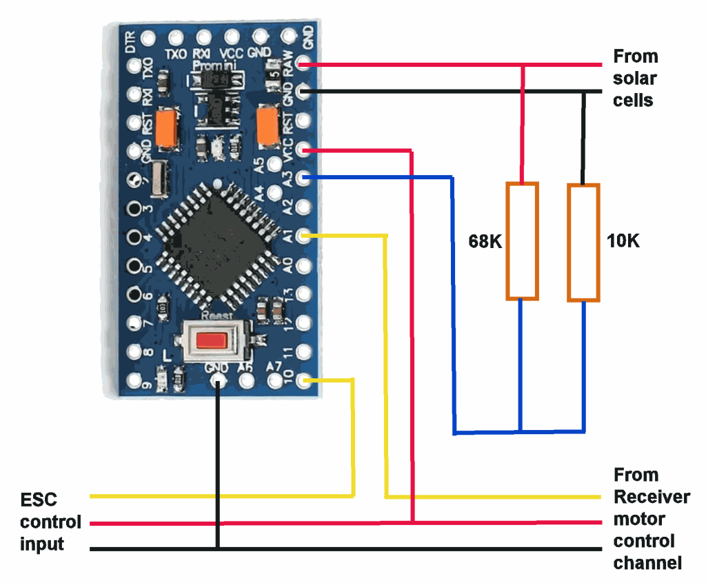
The two resistors scale down the input voltage from the solar cells to one of the Arduino’s analog input pins, A3. Say there is 6.0V coming from the cells, then the voltage at A3 is:
6.0V x 10K / (10K + 68K) = 0.769V
The Arduino is configured to use its internal 1.1V reference voltage for performing the analog measurement, so with the 10K / (10K + 68K) voltage divider, its able to measure solar cell voltages up to 8.58V. This allows up to twelve solar cells to be used, and also allows a 2-cell LiPo battery to be substituted for the solar cells, when testing.
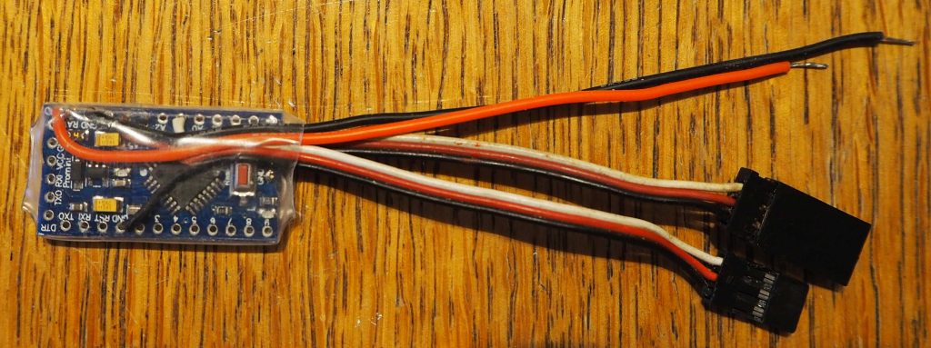
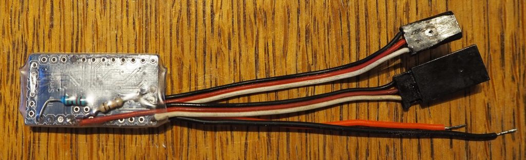
The resistors and wires are just soldered direct to the Arduino board, and to each other.
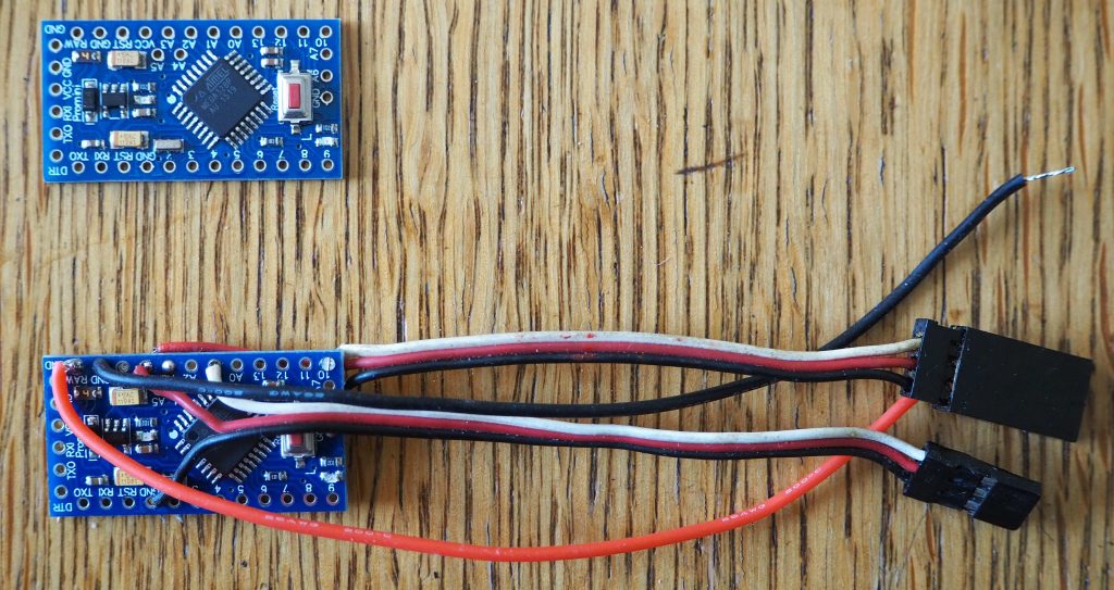
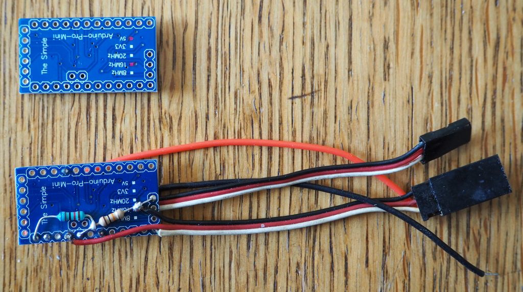
Above you can see photos of the top and bottom of a bare Pro Mini, and one assembled into a solar regulator. Below you see photos of the finished regulator, covered in heatshink tubing, and ready to be installed in the plane.
The program (called a “sketch” in Arduino terminology) is here. You don’t need to understand it to use it. Just use the free Arduino IDE to Upload it to your Arduino board. You can look to see how the program works by examining it in the IDE, if you want. There are quite a few comments included, that explain the connections, etc. There’s a zipped version of the sketch, in its folder here:
https://ceptimus.co.uk/solarRegulator.zip
The program samples the available solar cell voltage for the first ten seconds after it’s switched on, so during that time you should avoid using any throttle input (keep the transmitter motor control at the “stopped” position. You can also hold up the plane so that the full available light falls on the solar cells, without any shadow covering some of the cells. It’s not that critical, because, provided the motor is stopped, the difference in voltage between full sun and subdued light is minimal. The main reason the program samples for ten seconds is to allow it cater for slight differences in the tolerance of the resistors that divide the voltage, and to allow the program to automatically cater for ten, eleven, or twelve solar cells. You could use more than twelve cells, but you’d need to increase the 68K resistor so the Arduino has sufficient (scaled) measuring range to measure the highest solar cell voltage it ever sees.
You can test the operation of the regulator by moving the transmitter throttle stick to full power (beware propeller) and then moving the plane so that more or less sunlight falls directly on the cells. As a test, you can plug the ESC control input direct to your receiver, so that the motor operates unregulated. Now you will see the motor doing things like stalling when a shadow falls on the cells, and the motor might instantaneously draw an excess of power, causing the servos to stop working, or the receiver temporarilly losing power, causing loss of control.
Flying
Have your transmitter switched on and transmitting, with the motor control set to stopped. Connect the solar cells to the electronics. You need some sort of connector or switch, to stop the servos from jittering when you’re not flying: a connector, such as an XT30, is more reliable than a switch, and allows a battery to be substituted for indoor tests and setting up. Hold the plane with the solar cells facing the best available light for some time during the first ten seconds from connecting. After ten seconds have elapsed, you can try the motor control and do your other usual preflight checks. When you launch the plane, don’t try to climb quickly. Remember there is not an excess of power available, and you will only stall the plane if you overdo the climb. You get most power when the sunlight is falling as perpendicularly as possible onto the cells: if your flying site and conditions allow, you usually get the best climb when flying away from the sun. Avoid flying through any cloud shadows, where possible. When making gentle S-turns during the climb, you can fly at right angles from the sun during the straight parts, and turn either way at the ends. If you turn towards the sun, you get the best power possible in the first part of the turn, so if you’re very low, that’s the safest direction. Of course, there is then less power available during the later part of the turn: if you turn away from the sun, it’s the other way round, with less power at the start of the turn and more towards the end. You’ll soon find what works best, from experience.
There’s a thread on the Mode Zero forum containing posts from Mike and I. There are even videos of the planes flying!
https://mode-zero.uk/viewtopic.php?f=61&t=402
Good luck! Please use the form below to leave any questions or comments, and I’ll do my best to answer them.
Leave a Reply