These posts relate to the previous few concerning the Banggood kit: Cross LED Dot Matrix Display Circuit Board Rotating Electronic Kit
It uses an STC89C52RC microcontroller which is a (fairly) modern Chinese version in the 8051 family.
You can program it in assembler, but I chose to use the C language for this project.
The font
We’re going to be displaying text so we need some kind of font. The kit provides 16 LEDs arranged vertically on each of the two arms, but I thought that if we use characters the full height of the arms then we wouldn’t be able to fit many of these large characters around the cylinder that the arms sweep out (unless the characters were ridiculously skinny for their height) so I decided to use an 8×8 font which would allow for two rows of characters.
For simplicity I wanted the characters defined in the font to include the spacing to the left and/or right of normal characters so most characters in the font are only 7 pixels wide – or even less for skinny characters such as i – and only a few characters like q and y have descenders, so the spacing between the two rows of characters is included in the font too.
The kit sensibly arranges the pins driving the LEDs so that the chip’s four 8-bit I/O ports, P0, P1, P2, P3 each drive either the top 8 LEDS or the bottom 8 LEDs on an arm: one arm has P2 on the top and P0 on the bottom, the other arm has P1 at the top and P3 at the bottom (at least that’s the way mine turned out). I chose to fit all blue LEDs to the P0/P2 arm and all red LEDs to the other one – obviously you can fit them in other ways – it might look pretty to get two extra colours – then you might have (say) yellow and green on the top row with red and blue on the bottom.
Anyway, each of the four ports has the least significant bit at the top, and then the bits going in order down to the most significant bit at the bottom. If you wire up the motor with the red wire as positive, the board spins clockwise (viewed from above) so the LEDs scan the characters out in right-to-left order. The wiring is such that the program has to write a ‘0’ to an I/O pin to illuminate the corresponding pin, or write a ‘1’ to switch it off. It’s convenient to write 8-bit quantities in hexadecimal and in the C language we write 0xFF to indicate all 8 bits high or 0x00 for all eight bits low.
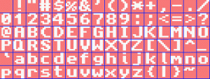
I searched on line and found this 8×8 font which I thought would be suitable:
 The font is on this page and includes the data in C-friendly form http://www.coranac.com/tonc/text/text.htm
I had to manipulate the font data for right-to-left scan order with the least significant bit at the top and a zero-bit indicating ‘LED on’. I wrote a C# program to do that.
Note that the font starts with the space character (ASCII 32) and is in ASCII order. The last character (ASCII 127 [DEL]) renders a space too, but as that’s a duplicate you could tweak it to get a £ or € or some other symbol you might want to display.
Say our program wants to display the number 2 This is the ASCII character 50. Our font doesn’t have characters defined for the first 32 ASCII values so we subtract 32 to get 18 and then multiply by 8 (eight bytes per character in the table) to get 144. The data we need to display a 2 therefore starts 144 bytes into the font table and consists of the eight bytes:
0xFF,0xB9,0xB0,0xA6,0x8E,0x9C,0xBD,0xFF
So the program outputs those eight bytes in that order and (remembering that the arms scan out the characters from right to left) we get:

Leave a Reply