Lots of people know about curves of constant width – for example the UK 50p and 20p coins: despite their apparent non-roundness they have constant width when measured by parallel jawed calipers or the mechanisms inside vending machines. If the shapes of these coins are extruded as prisms they can be used as rollers for moving heavy equipment around on hard floors.
 The Reuleaux Triangle, pictured above is the best known curve of constant width (other than the circle, of course). Notice in the animation above the triangle never quite reaches into the corners of the square, but it does remain in contact with all four sides of the square at all times.
In terms of three-dimensional solids the Reuleaux Tetrahedron is the analogue of the Reuleaux Triangle, but it is NOT a solid of constant width – it comes close but the edges stick out a bit too much: it’s about 2.5% wider across the midpoints of two edges than it is from a vertex to the opposite face.
 You can produce solids of constant width fairly easily by rotating a curve of constant width – imagine spinning a 50p coin on its edge: providing the same point of the edge remains in contact with the surface it is spinning on, the volume swept out by the coin is a solid of constant width. However these kind of solids are fairly boring because cross-sections perpendicular to the axis of rotation are just circles.
Much more interesting are the Meissner Tetrahedra. In 1911 the Swiss mathematician, Ernst Meißner demonstrated how the Reuleaux Tetrahedron could be patched by rounding off three of its edges to produce true solids of constant width: there are two ways of doing it: one where the three rounded edges share a common vertex, and the other where the three rounded edges are around one face of the tetrahedron.
I set out to model the tetrahedra using the OpenSCAD CAD program, so that they could be printed on a 3D printer. OpenSCAD is free software available for Linux/UNIX, Windows and Mac OS X. I recommend it.
So we start with the Reuleaux Tetrahedron. It’s fairly easy to model as it’s formed by the intersection of four spheres with their centres located at the vertices of a regular tetrahedron where all the tetrahedron edges have the same length as the radius of the spheres. As we’re making solids of constant width we name the radii of the spheres, ‘width’, and the edge lengths of the tetrahedron are also ‘width’. This is a little disorienting at first, but you get used to it.
Wikipedia gives the Cartesian coordinates for the vertices of a tetrahedron falling on the unit sphere with the lower face level as:
v1 = ( sqrt(8/9), 0 , -1/3 )
v2 = ( -sqrt(2/9), sqrt(2/3), -1/3 )
v3 = ( -sqrt(2/9), -sqrt(2/3), -1/3 )
v4 = ( 0 , 0 , 1 )
with the edge length of sqrt(8/3).
Building that information into an OpenSCAD model and allowing for scaling the resulting Reuleaux Tetrahedron to any desired size gives the code:
// Reuleaux Tetrahedron
// ceptimus 2018-01-13

width = 50; // width of the object to be printed
$fn = 50; // higher numbers give smoother object but (much) longer render times

// vertices and edge length of Reuleaux Tetrahedron from Wikipedia
v1 = [sqrt(8/9), 0, -1/3];
v2 = [-sqrt(2/9), sqrt(2/3), -1/3];
v3 = [-sqrt(2/9), -sqrt(2/3), -1/3];
v4 = [0, 0, 1];
a = sqrt(8/3); // edge length given by above vertices

k = width / a; // scaling constant to generate desired width from standard vertices

reuleauxTetrahedron();

module reuleauxTetrahedron() {
    intersection() {
        translate(v1 * k)
            sphere(r = width);
        translate(v2 * k)
            sphere(r = width);
        translate(v3 * k)
            sphere(r = width);
        translate(v4 * k)
            rotate([90, 0, 0]) // use similar part of sphere for bottom face as other faces - OpenScad renders the parts of 'spheres' near the 'poles' differently
                sphere(r = width);
    }
}
…which results in this view:
 If we alter the $fn parameter we can make it much smoother. With $fn = 300; it still previews (F5) almost instantly but rendering (F6) takes a long time unless you have a very fast machine.
 Now for the changes necessary to round off some edges to make it a true solid of constant width. If we take one of the faces of the underlying tetrahedron and continue it out till it cuts one of the spherical faces of the Reuleaux Tetrahedron we get this two dimensional shape for the portion of that flat face between the triangle and the curved outer surface.
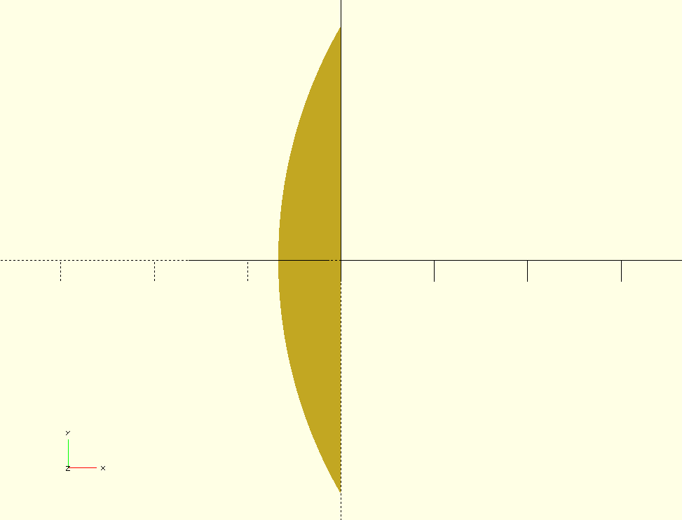 Here’s the code that produces that shape:
intersection() {
    // 6 is just an empirical 'big enough' figure so that the arc is contained within the rectangle
    translate([-width / 6, -sqrt(2/3) * k, 0])
        square([width / 6, width]);
    translate([(sqrt(2/9) + sqrt(8/9)) * k, 0, 0])
        circle(r = width);
}
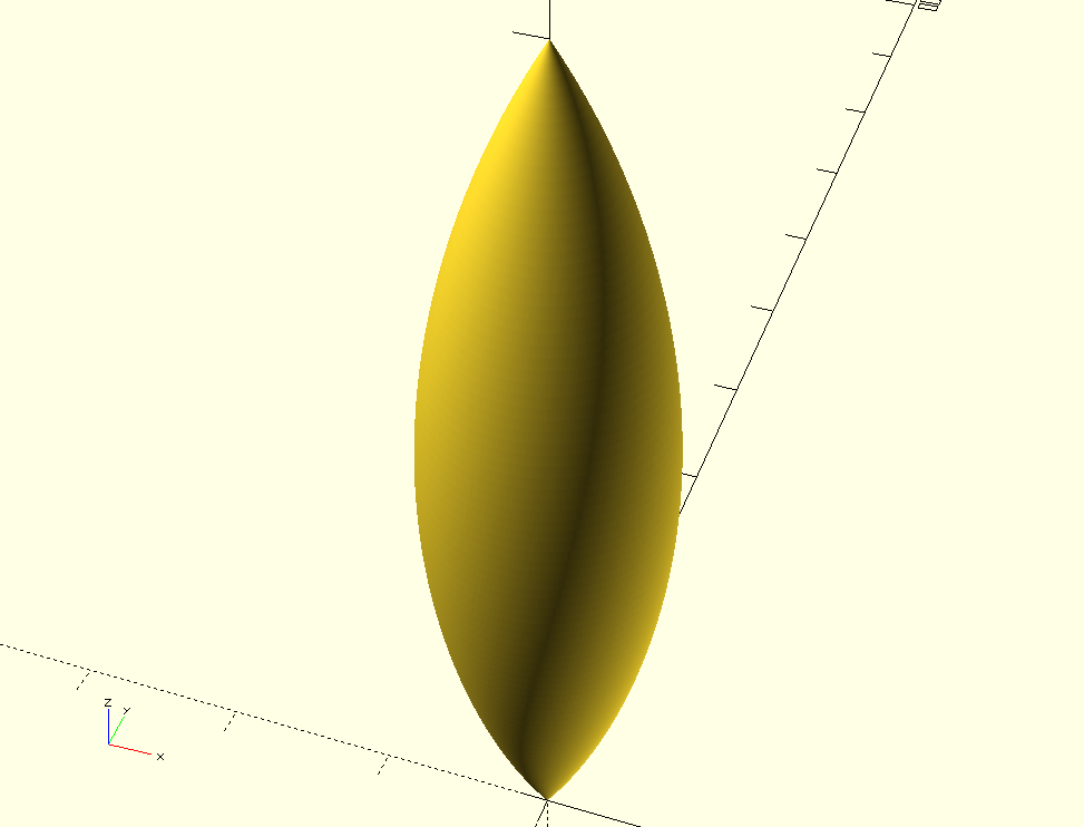
And we can use OpenSCAD’s rotate_extrude() to spin that shape around and produce the three dimensional shape I call a ‘spindle’ – which is the shape we need to round off three of the Reuleaux Tetrahedron’s edges so as to make it constant width.
Now we need to lean the spindle over and line its two vertices up with two vertices of the tetrahedron to round off the edges, but first we need to remove some of the edge material of the tetrahedron that would otherwise project out beyond the spindle. To do this we introduce the angle, alpha, which is half the angle formed by any two intersecting regular (not curved) tetrahedron faces. This angle of a tetrahedron is called the ‘dihedral angle’ and alpha is half of that – about 35.2644 degrees.
My sketch makes a wedge shape with the dihedral angle (2 x alpha) for the front edge of the wedge and the wedge long enough to fit against one edge of the underlying tetrahedron and deep enough to ‘include’ all the material we need to cut away from one edge of the Reuleaux Tetrahedron before inserting the spindle. Here’s what the tetrahedron looks like when the wedge is shown in its ‘cutting position’.
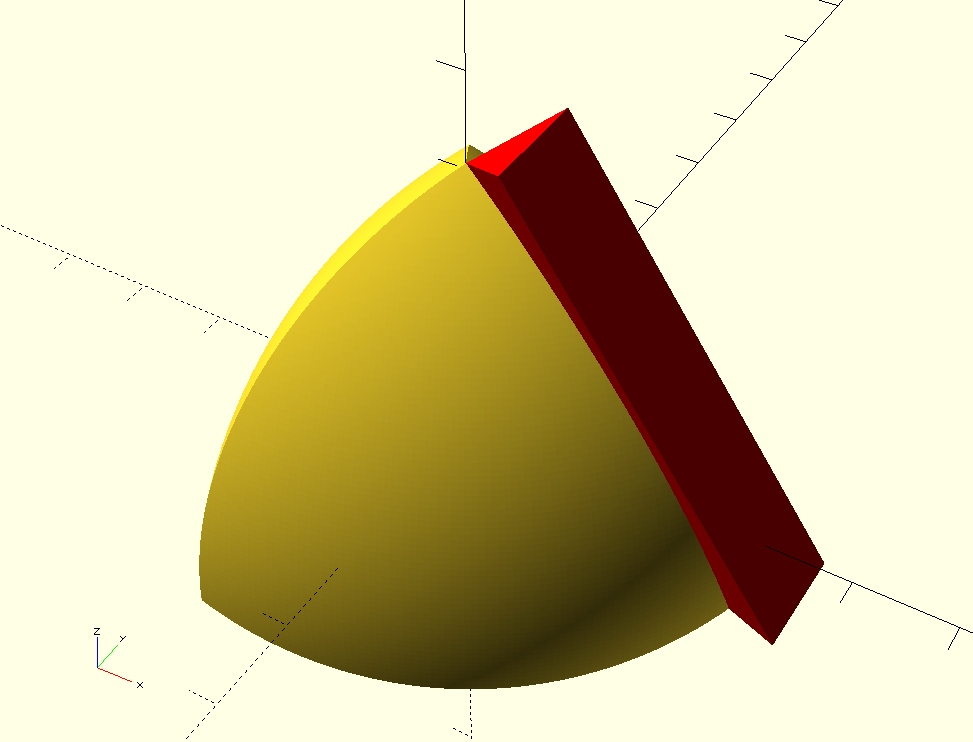 And here’s the code that does it:
alpha = atan(2 * sqrt(2)) / 2; // half 'dihedral angle' (amount the three edges up to the apex lean inwards from the vertical)

reuleauxTetrahedron();
color([1, 0, 0])
    translate(v1 * k)
        rotate([0, -alpha, 0])
            wedge();

module wedge() { // used to subtract three sharp edges of Reuleaux Tetrahedron prior to adding the rounded 'spindle' edges
    hull() {
        rotate([0, 0, -alpha])
            // 5 is just an empirical 'big enough' figure so that the wedge includes the Reuleaux Tetrahedron edge when placed appropriately
            cube([width/5, 0.001, width]);
        rotate([0, 0, alpha])
            translate([0, -0.001, 0])
                cube([width/5, 0.001, width]);
    }
}
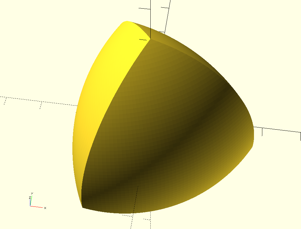
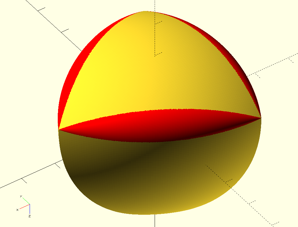
Now we can use OpenSCAD’s difference() function to subtract the wedge away from the Reuleaux Tetrahedron.
 And then put the spindle in place to patch the edge.
 Repeat that procedure three times and we’ve completed one of the two varieties of Meissner Tetrahedron.
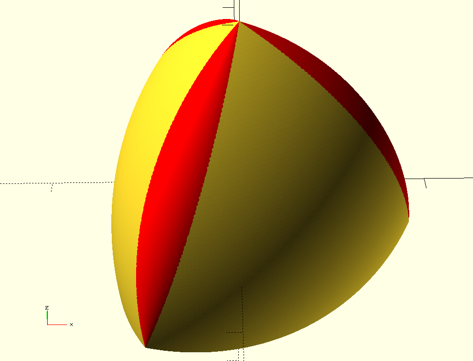 Note that only three of the edges are rounded – the bottom (far) three edges are still sharp – if you were to round those off as well then the resulting solid WOULDN’T have constant width – the distance between opposite ‘edges’ would then be too small.
Here’s the complete code for the finished Meissner Tetrahedron. Remember that you can increase the value of $fn to get a smoother rendering, but that although the preview (F5) will still work fast enough, the rendering (F6) can bring even a fast PC to its knees.
// Meissner Tetrahedron (solid of constant width) - common vertex variant
// ceptimus 2018-01-13

width = 50; // width of the object to be printed
$fn = 50; // higher numbers give smoother object but (much) longer render times

// vertices and edge length of Reuleaux Tetrahedron from Wikipedia
v1 = [sqrt(8/9), 0, -1/3];
v2 = [-sqrt(2/9), sqrt(2/3), -1/3];
v3 = [-sqrt(2/9), -sqrt(2/3), -1/3];
v4 = [0, 0, 1];
a = sqrt(8/3); // edge length given by above vertices

k = width / a; // scaling constant to generate desired width from standard vertices

alpha = atan(2 * sqrt(2)) / 2; // half 'dihedral angle' (amount the three edges up to the apex lean inwards from the vertical)

difference() {
    reuleauxTetrahedron();
    for (angle = [0 : 120 : 240])
        rotate([0, 0, angle])
            translate(v1 * k)
                rotate([0, -alpha, 0])
                    wedge();
}
color([1, 0, 0])
    for (angle = [0 : 120 : 240])
        rotate([0, 0, angle])
            translate(v1 * k)
                rotate([0, -alpha, 0])
                    spindle();

module reuleauxTetrahedron() {
    intersection() {
        translate(v1 * k)
            sphere(r = width);
        translate(v2 * k)
            sphere(r = width);
        translate(v3 * k)
            sphere(r = width);
        translate(v4 * k)
            rotate([90, 0, 0]) // use similar part of sphere for bottom face as other faces - OpenSCAD renders the parts of 'spheres' near the 'poles' differently
                sphere(r = width);
    }
}

module wedge() { // used to subtract three sharp edges of Reuleaux Tetrahedron prior to adding the rounded 'spindle' edges
    hull() {
        rotate([0, 0, -alpha])
            // 5 is just an empirical 'big enough' figure so that the wedge includes the Reuleaux Tetrahedron edge when placed appropriately
            cube([width/5, 0.001, width]);
        rotate([0, 0, alpha])
            translate([0, -0.001, 0])
                cube([width/5, 0.001, width]);
    }
}

// rotate the curve produced where the Reuleaux Tetrahedron surface intersects with the (extended) underlying tetrahedron face
// this produces the correct spindle shape for rounding off three edges of the Reuleaux Tetrahedron to produce the Meissner Tetrahedron
module spindle() {
    translate([0, 0, width/2])
        rotate_extrude()
            intersection() {
                // 6 is just an empirical 'big enough' figure so that the arc is contained within the rectangle
                translate([-width / 6, -sqrt(2/3) * k, 0])
                    square([width / 6, width]);
                translate([(sqrt(2/9) + sqrt(8/9)) * k, 0, 0])
                    circle(r = width);
            }
}
Here’s the second variant where the three rounded edges are in a triangle rather than sharing a common vertex.
Here are the OpenSCAD files for the two variants.
Leave a Reply